



IN401- Network III
md33 min readSummary of IN403
Chapter 1- TCP
A Network is a set of devices connected together.
Types of Networks
- LAN (Local Area Network): A network that connects devices within a limited area such as a home, school, or office building.
- WAN (Wide Area Network): A network that covers a broad area (e.g., any network whose communications links cross metropolitan, regional, or national boundaries over a long distance).
- MAN (Metropolitan Area Network): A network that connects users in a geographic area or region larger than that covered by even a large local area network (LAN) but smaller than the area covered by a wide area network (WAN).
- PAN (Personal Area Network): A network for interconnecting devices centered around an individual person's workspace.
Network Topologies
- Star Topology: All devices are connected to a central hub.
- Bus Topology: All devices are connected to a single central cable, called the bus or backbone.
- Ring Topology: Each device is connected to two other devices, forming a circular data path.
- Mesh Topology: Every device is connected to every other device in the network.
- Hybrid Topology: A combination of two or more different types of topologies.
Network Devices
- Router: A device that forwards data packets between computer networks, creating an overlay internetwork.
- Switch: A device that filters and forwards packets between LAN segments.
- Hub: A basic networking device that connects multiple Ethernet devices, making them act as a single network segment.
- Modem: A device that modulates and demodulates signals for data transmission over telephone lines.
- Access Point: A device that allows wireless devices to connect to a wired network using Wi-Fi or related standards.
- others...
Network Layers
- Physical Layer: Deals with the physical connection between devices and the transmission of binary data over physical media.
- Data Link Layer: Responsible for node-to-node data transfer and error detection/correction.
- Network Layer: Manages device addressing, tracks the location of devices on the network, and determines the best way to move data.
- Transport Layer: Provides reliable data transfer services to the upper layers.
- Session Layer: Manages sessions between applications.
- Presentation Layer: Translates data between the application layer and the network format.
- Application Layer: Provides network services directly to end-user applications.
Models & Layers Comparison
Encapsulation
Data encapsulation is the process of wrapping data with protocol information at each layer of the OSI or TCP/IP model.
Congestion Control
Congestion control ensures the sender does not overwhelm the network. It uses a Congestion Window (cwnd).
TCP Phases
Slow Start: Exponential growth (CWND doubles every RTT). Starts at 1 MSS.
Congestion Avoidance: Linear growth (CWND + 1 MSS per RTT). Happens after reaching the threshold (ssthresh).
Congestion Detection:
- Timeout: Severe congestion (packet lost, no ACKs).
- 3 Duplicate ACKs: Mild congestion (packet lost, but others arrived).
Visual Comparison: Tahoe vs. Reno
TCP Tahoe (The "Panic" Approach): On any loss (Timeout OR 3 Dup ACKs), it resets cwnd to 1 and enters Slow Start.
TCP Reno (The "Smart" Approach):
On Timeout: Resets cwnd to 1 (like Tahoe).
On 3 Dup ACKs (Fast Recovery): Halves the cwnd (cwnd = cwnd / 2) and enters Congestion Avoidance immediately. It skips Slow Start.
TCP Tahoe Graph (Always resets to 1)
Note: At Round 6, a loss occurs. Tahoe drops immediately to 1.
TCP Reno Graph (Fast Recovery)
Note: At Round 6, "3 Duplicate ACKs" occur. Reno cuts CWND in half (to 5) and grows linearly (Congestion Avoidance), avoiding the slow start restart.
Key Differences
| Feature | TCP Tahoe | TCP Reno |
|---|---|---|
| Response to Timeout | Reset cwnd to 1 (Slow Start) |
Reset cwnd to 1 (Slow Start) |
| Response to 3 Dup ACKs | Reset cwnd to 1 (Slow Start) |
Fast Recovery: cwnd = cwnd / 2, then linear growth |
| Philosophy | Assumes all loss is severe congestion. | Distinguishes between severe loss (Timeout) and sporadic loss (Dup ACKs). |
3-Way Handshake
The TCP 3-way handshake is used to establish a reliable connection between a client and server.
- SYN: The client sends a SYN (synchronize) packet to the server to initiate a connection.
- SYN-ACK: The server responds with a SYN-ACK (synchronize-acknowledge) packet to acknowledge the client's request and synchronize its own sequence number.
- ACK: The client sends an ACK (acknowledge) packet back to the server to confirm the connection is established.
RTT Estimation and Timeout Calculation
TCP uses Round-Trip Time (RTT) measurements to set retransmission timeouts adaptively.
The Formulas
-
EstimatedRTT: Exponential Weighted Moving Average (EWMA) of sample RTTs.
- Formula:
EstimatedRTT = (1 - α) × EstimatedRTT + α × SampleRTT - Typical value:
α = 0.125(weights recent samples more heavily)
- Formula:
-
DevRTT: Deviation (variability) of RTT.
- Formula:
DevRTT = (1 - β) × DevRTT + β × |SampleRTT - EstimatedRTT| - Typical value:
β = 0.25
- Formula:
-
TimeoutInterval: The actual timeout value used.
- Formula:
TimeoutInterval = EstimatedRTT + 4 × DevRTT - The
4 × DevRTTterm provides a safety margin for variance.
- Formula:
TCP Timer Management
Karn's Algorithm: Do not use RTT samples from retransmitted segments (ambiguous which transmission the ACK corresponds to).
Exponential Backoff: When a timeout occurs:
- The timeout interval is doubled for the retransmission.
- Prevents further timeouts during congestion.
- Resets to calculated value once valid ACK is received.
Example: If timeout = 1s and packet is lost, next timeout = 2s, then 4s, then 8s, etc.
Deep Dive: 3-Way Handshake Mechanics & Scenarios
How ACKs Work in the Header
An "ACK" isn't a separate packet type; it's just a segment with the ACK Flag set to 1 and a value in the Acknowledgement Number field.
- Piggybacking: The ACK for received data is often "piggybacked" onto an outgoing data segment to save bandwidth.
- Cumulative: The ACK number is always the Next Expected Byte. If you receive byte 100, you send
ACK = 101.
Scenario A: The "Happy Path" (Normal Connection)
- Client: Sends
SYN=1,Seq=x(Random). No data allowed. - Server: Sends
SYN=1,ACK=1.Seq=y(Server's own random start).Ack=x+1(Confirming client's SYN).- Note: The server must allocate memory (buffers) at this stage.
- Client: Sends
ACK=1.Seq=x+1.Ack=y+1(Confirming server's SYN).- Note: This 3rd packet can carry application data (e.g., the HTTP request).
Scenario B: The "Closed Door" (Connection Refused)
What happens if the Client sends a SYN to a port where no application is listening (e.g., port 8080 is closed)?
- Server Response: It does not ignore the packet. It replies with a RST (Reset) segment.
- Meaning: "No one is home. Stop trying." The client immediately aborts; no teardown is needed.
Scenario C: Packet Loss during Handshake
-
Lost SYN: Client gets no response. It assumes the packet was lost and retransmits the SYN after a timeout.
-
Lost SYN-ACK:
- Client thinks its SYN was lost (retransmits SYN).
- Server thinks its SYN-ACK was lost (retransmits SYN-ACK).
-
Lost Final ACK:
- Server remains in
SYN_RCVDstate. - Server eventually times out and retransmits the SYN-ACK.
- Edge Case: If the client tries to send data immediately after the lost ACK, the server receives data for a connection it thinks isn't open yet. The server usually ignores the data until the handshake completes (or accepts it if the implementation allows "fast open").
- Server remains in
Scenario D: Security & Random ISNs
Why use Random Initial Sequence Numbers (ISN) instead of starting at 0?
- Prevention of "Old" Packet Confusion: If a connection closes and immediately reopens, a stray packet from the old connection (delayed in the network) might arrive with
Seq=100. If the new connection also started at 0 and is currently at 100, that old packet would be accepted as valid data, corrupting the file. - Anti-Spoofing / Hijacking: If ISNs were predictable (e.g., always 0), an attacker could easily spoof a connection by guessing the sequence numbers. Randomness makes this much harder.
Scenario E: SYN Flood Attack (Denial of Service)
-
Attack: Attacker sends thousands of
SYNpackets with fake (spoofed) IP addresses. -
Result: Server replies with
SYN-ACKand allocates memory (buffers) for every request, waiting for the finalACKthat never comes. -
Impact: Server runs out of memory/resources and crashes or stops accepting legitimate connections.
-
Defense: SYN Cookies (Server doesn't allocate memory immediately; instead, it encodes the state into the Initial Sequence Number itself).
Chapter 2- Quality of Service (QoS)
The Need for QoS
IP networks are traditionally "Best Effort" (no guarantees). QoS is essential to manage limited resources and ensure performance for critical applications (Voice, Video) by managing four key metrics:
-
Bandwidth: The capacity of the link. Lack of bandwidth causes congestion.
-
Packet Loss: Occurs when buffers overflow.
-
Impact: Video pixelization, choppy audio, retransmissions (TCP).
-
Latency (Delay): Time taken from source to destination.
-
Real-time Requirement: ITU recommends < 150 ms for voice/video.
-
Types: Propagation (distance), Serialization (link speed), Processing (router CPU), Queuing (congestion).
-
Jitter (Delay Variation): The difference in delay between consecutive packets.
-
Solution: Jitter buffers (but these add delay).
QoS Models: IntServ vs. DiffServ
There are three main models for handling traffic: Best Effort, IntServ, and DiffServ.
| Feature | IntServ (Integrated Services) | DiffServ (Differentiated Services) |
|---|---|---|
| Philosophy | Reservation (Hard QoS). Signals the network to reserve bandwidth per flow. | Categorization (Soft QoS). Classifies packets into groups and treats groups differently. |
| Scalability | Low. Core routers must maintain state for every flow. Good for small networks. | High. Core routers only look at the class (DSCP mark), not individual flows. |
| Protocol | Uses RSVP (Resource ReSerVation Protocol). | Uses DSCP (Differentiated Services Code Point). |
| Analogy | Reserving a specific seat on a train. | Buying a "First Class" ticket (guarantees a type of seat, not a specific one). |
IntServ Components
- RSVP: The signaling protocol.
- PATH Message: Sender Receiver (Carries TSpec: Traffic Specification).
- RESV Message: Receiver Sender (Carries RSpec: Reservation Specification).
- Services:
- Guaranteed Service: Hard bound on delay (for real-time apps).
- Controlled Load: Emulates a lightly loaded network (best effort but "better").
Classification & Marking (DiffServ)
Packets are marked at the Edge so Core routers know how to treat them.
L3 Marking: DSCP (Differentiated Services Code Point)
Uses the 6-bit ToS field in the IP Header.
-
PHB (Per-Hop Behavior): The treatment a packet gets based on its mark.
-
EF (Expedited Forwarding): Low latency, low jitter, guaranteed bandwidth (e.g., Voice).
-
AF (Assured Forwarding): 4 Classes, 3 Drop Probabilities.
-
Formula:
AFxywherex= Class (Priority) andy= Drop Probability (High y = High drop chance). -
Example: AF41 is better than AF11 (Higher Priority). AF13 is dropped before AF11 (Higher Drop Prob).
-
CS (Class Selector): Backward compatible with old IP Precedence.
Traffic Management Mechanisms
Policing vs. Shaping
Both control traffic rates, but they handle "excess" traffic differently.
- Policing: Drops excess packets (Strict). "Speed limit enforcement".
- Shaping: Buffers (delays) excess packets (Smooth). "Stoplight metering".
The Token Bucket Algorithm
Used for Policing/Shaping.
-
Bucket Size (b): Represents maximum Burst Size.
-
Token Rate (r): Represents Average Rate.
-
Math: In a time interval
t, the max data allowed is: -
Concept: Tokens fill the bucket at rate
r. To send a packet, you need a token. If the bucket is full, tokens overflow (waste). If the bucket is empty, you wait (shape) or drop (police).
Congestion Management (Queuing)
How to handle packets when the buffer is full.
- FIFO: First In, First Out. No QoS.
- PQ (Priority Queuing): Strict priority. High priority always goes first. Risk: Starvation of lower queues.
- WFQ (Weighted Fair Queuing): Fair sharing. Each flow gets a % of bandwidth.
- CBWFQ / LLQ: The modern standard. Mixes strict priority (for Voice) with fair sharing (for Data).
Congestion Avoidance
- Tail Drop: The default. When the queue is full, drop new packets. Bad: Causes "TCP Global Synchronization" (all streams slow down at once).
- RED (Random Early Detection): Randomly drops packets before the queue is full to signal TCP to slow down gracefully.
IPv6
-
Why IPv6? Developed because IPv4 addresses are running out. With the rise of IoT and internet-connected devices, the 32-bit space of IPv4 is insufficient. IPv6 solves this with a massive 128-bit address space.
-
Addressing Format:
- Written in Hexadecimal (0-9, A-F).
- Format:
x:x:x:x:x:x:x:x(8 groups of 4 hex digits).
-
Notation Rules:
- Omit Leading Zeros:
01ab→1ab. - Double Colon (
::): Replaces one contiguous string of all-zero segments (e.g.,1:0:0:0:1→1::1). Can only be used once.
- Omit Leading Zeros:
-
Address Types:
- Unicast: One-to-One.
- Multicast: One-to-Many.
- Anycast: One-to-Nearest (assigned to multiple devices; routed to the closest one).
- Note: There is NO Broadcast in IPv6 (Multicast is used instead).
-
Key Features:
- Simpler Header: Fixed 40 bytes (vs. IPv4's variable 20+ bytes) for faster processing.
- Autoconfiguration: Supports SLAAC (Stateless) and DHCPv6 (Stateful).
- Security: Built-in IPSec support.
- Flow Label & Traffic Class: Support for QoS and flow identification.
IPv6 Header: Flow Label & Traffic Class
The IPv6 header includes two fields specifically designed for Quality of Service (QoS) support:
Traffic Class (8 bits)
- Purpose: Similar to the DSCP field in IPv4.
- Function: Allows routers to classify and prioritize packets.
- Usage: Can mark packets for differentiated services (e.g., Voice = High Priority, Bulk Data = Low Priority).
- Compatibility: Works with DiffServ (Differentiated Services).
Flow Label (20 bits)
- Purpose: Identifies packets belonging to the same flow (stream of packets from source to destination requiring special handling).
- Function: Allows routers to provide consistent treatment for all packets in a flow without examining upper-layer headers.
- Benefits:
- Faster Processing: Routers can make forwarding decisions based on the Flow Label alone.
- QoS Support: Works with IntServ/RSVP to reserve resources for specific flows.
- Load Balancing: Can be used for Equal-Cost Multi-Path (ECMP) routing decisions.
Example: A video streaming session can have all its packets tagged with the same Flow Label, ensuring they all receive the same low-latency treatment.
Flow Label Usage Scenarios
| Scenario | How Flow Label Helps |
|---|---|
| Real-Time Streaming | All packets in a video call share the same Flow Label → routers apply consistent low-latency treatment |
| ECMP Load Balancing | Routers use Flow Label to hash and distribute flows across multiple equal-cost paths (keeps packets in same flow on same path) |
| Resource Reservation (RSVP) | Flow Label identifies the flow for which bandwidth has been reserved |
| Firewall Optimization | Firewalls can make decisions based on Flow Label without deep packet inspection |
Note: The combination of Traffic Class (DiffServ marking) and Flow Label (flow identification) makes IPv6 inherently more QoS-friendly than IPv4.
IPv6 Address Anatomy & Compression
Chapter 3- Network Function Virtualization (NFV)
1. The Concept
NFV replaces dedicated hardware appliances (proprietary "middleboxes") with software-based Virtual Network Functions (VNFs) running on standard commodity servers (COTS - Commercial Off-The-Shelf).
- Traditional: One physical node per role (Router, Firewall, DPI). Hard to scale, expensive.
- Virtualized: Generic hardware runs multiple functions as software. Flexible, scalable.
2. Benefits (Why do it?)
-
Cost Reduction: Lowers CAPEX (less hardware to buy) and OPEX (less power/space/maintenance).
-
Agility: Rapid deployment of new services (just software installation).
-
Scalability: Elasticity (scale up/down on demand).
-
Vendor Independence: Decouples software from hardware (avoids vendor lock-in).
3. ETSI NFV Architecture (The Standard)
The framework defined by ETSI has three main blocks:
- NFVI (NFV Infrastructure): The foundation.
- Hardware: Compute (CPU), Storage, Network.
- Virtualization Layer: Hypervisor that abstracts hardware for the VNFs.
- VNFs (Virtualized Network Functions): The software applications.
- Examples: vRouter, vFirewall, vLoadBalancer.
- MANO (Management and Orchestration): The "Brain".
- NFV Orchestrator (NFVO): Manages the lifecycle of Network Services (chains of VNFs). Global view.
- VNF Manager (VNFM): Manages the lifecycle of individual VNFs (start, stop, scale).
- VIM (Virtualized Infrastructure Manager): Controls the hardware/resources (e.g., OpenStack).
Another View:
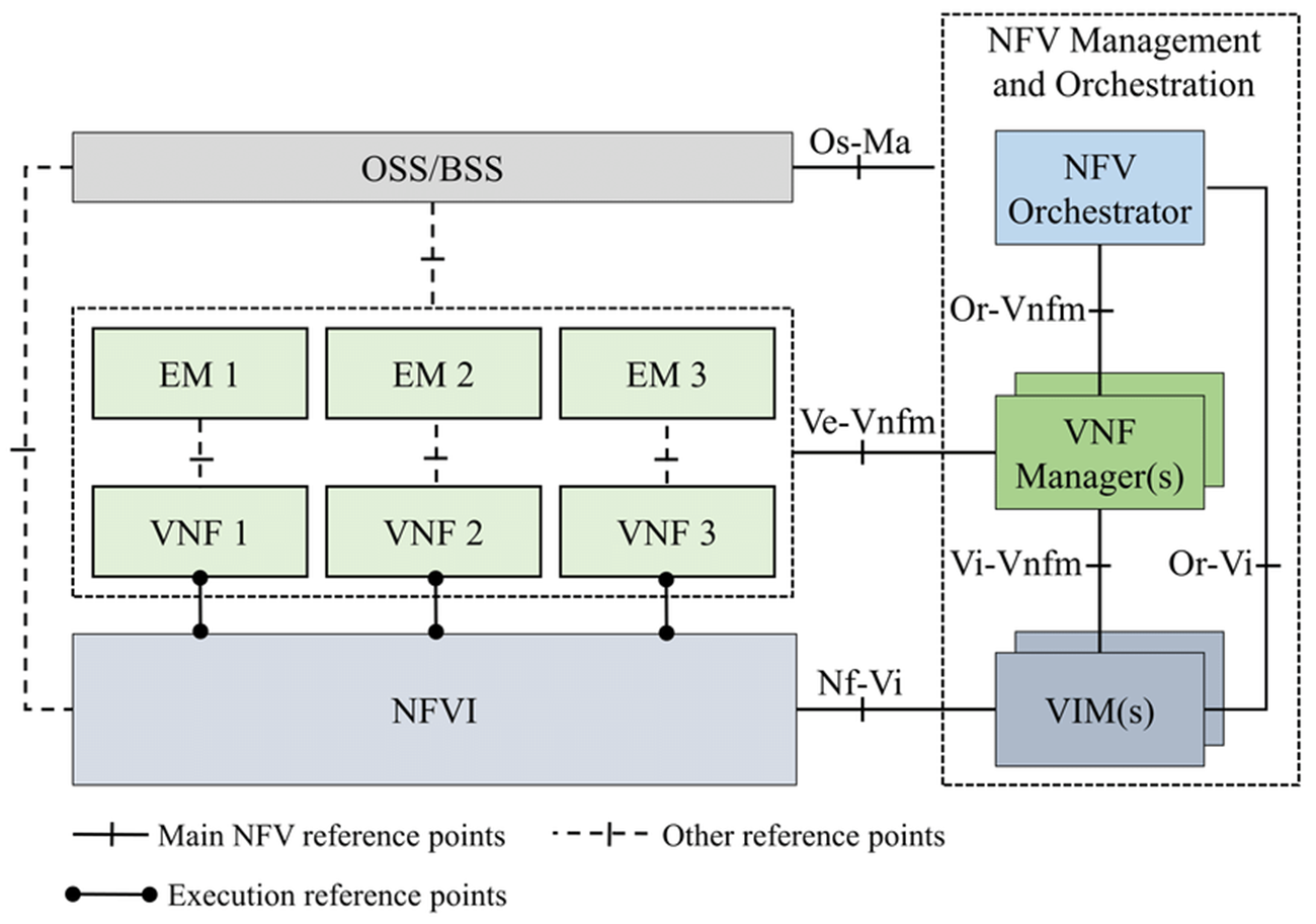
Component Breakdown
-
NFVI (NFV Infrastructure): The foundation that hosts the virtual machines.
- Hardware Resources: The physical Compute (CPU), Storage, and Network [switches].
- Virtualization Layer: The Hypervisor (like KVM or ESXi) or Container Engine (like Docker) that abstracts the hardware, allowing multiple VMs to share the same physical server.
-
VNF (Virtualized Network Function): The software application that performs the network function.
- Examples: vRouter, vFirewall, vLoadBalancer.
- Element Manager (EM): A small management agent specifically for the VNF [handles configuration and alarms for that specific app].
-
MANO (Management and Orchestration): The "brain of the operation," responsible for managing the lifecycle of resources and services. It has three sub-components:
- NFV Orchestrator (NFVO): The "Boss." It manages Network Services (chains of VNFs). It speaks to the OSS/BSS and decides when to create a new service.
- VNF Manager (VNFM): The "Supervisor." It manages the lifecycle of individual VNFs (instantiating, scaling, updating, and terminating them).
- VIM (Virtualized Infrastructure Manager): The "Resource Controller." It controls the NFVI (hardware/hypervisor). It allocates CPU, memory, and storage to the VMs. (Common example: OpenStack).
-
OSS/BSS (Operations/Business Support Systems): The external business layer.
- Handles billing, customer orders, and high-level service monitoring.
- It sends requests to the Orchestrator (e.g., "Customer A bought a firewall service, please set it up").
4. Key Components of MANO
- Instantiation: Creating and launching VNFs from a blueprint.
- Scaling: Auto-scaling services out (adding more instances) based on traffic.
- Healing: Restarting failed VNFs or moving them to healthy servers.
5. Use Cases
- 5G Core: Running 5G functions (UPF, SMF) as software.
- vCPE (Virtual Customer Premise Equipment): Replacing the box in your house/office with a virtual one in the cloud.
- IoT: Dynamic resource management for billions of devices.
Chapter 4: Software Defined Networking (SDN)
1. Introduction: The Paradigm Shift
SDN decouples the Control Plane (decision making) from the Data Plane (packet forwarding).
- Core Concept: "Software Defined" = Programmable. SDN exposes the control of the underlying system to upper-layer developers through an API.
Traditional Router Architecture
Monolithic & Proprietary:
- Tightly coupled data and control planes in a single device.
- Runs proprietary implementations of standard protocols (IP, OSPF, BGP) in proprietary OS (e.g., Cisco IOS).
- Control is distributed on a per-router basis.
Router Components:
- Input Ports: Line termination, data link protocols (Ethernet), lookup/forwarding (decentralized switching).
- Switching Fabric: Transfers packets from input to output buffers. Types: Memory, Bus, Crossbar.
- Output Ports: Buffers packets, scheduling disciplines to choose next packet for transmission.
Traditional Forwarding:
- Destination-Based: Forwarding based solely on destination IP address.
- Longest Prefix Matching: Finds the routing table entry matching the longest address prefix.
Why SDN?
- Innovation: Programmability promotes innovation in data centers, wireless, security.
- Simplification: Unified mechanism to manage "middleboxes" (firewalls, load balancers).
- Industry Evolution: Move from vertically integrated, proprietary systems to horizontal, open-interface model (like PC industry vs. mainframes).
Traditional vs. SDN
| Feature | Traditional Network | SDN |
|---|---|---|
| Control | Distributed (per-router) | Centralized (controller) |
| Hardware | Proprietary, vendor-locked | Commodity "white box" switches |
| Programmability | Limited (CLI configs) | Full (APIs, apps) |
| Innovation | Slow (vendor cycles) | Rapid (software updates) |
2. SDN Architecture (The 3 Layers)
3. The Data Plane: Generalized Forwarding
Key Functions:
- Forwarding: Moving packets from router's input to appropriate output (Data Plane).
- Routing: Determining end-to-end path from source to destination (Control Plane).
Switches use Flow Tables (Match + Action) instead of simple routing tables.
- Protocol: OpenFlow is the first and most widely adopted southbound API for SDN.
Flow Table Entry Structure
Each entry consists of:
- Pattern (Match): Header fields to match (MAC, IP, TCP/UDP ports, VLAN, etc.).
- Actions: What to do with matching packets (forward, drop, modify).
- Priority: Used when multiple patterns match.
- Counters: Statistics (bytes, packets matched).
Match-Plus-Action: Unifying Device Behavior
This abOpenFlow Protocol Details
OpenFlow is the standard southbound API for SDN communication between controller and switches.
Message Types
Controller-to-Switch:
- Features Request: Query switch capabilities.
- Configuration: Set switch parameters.
- Flow Mod (Modify): Add/delete/modify flow table entries.
- Statistics Request: Query counters, flow tables.
Asynchronous (Switch-to-Controller):
- Packet-In: Sent when a packet doesn't match any flow entry. Switch asks controller "What should I do?"
- Flow Removed: Notification when a flow entry expires or is deleted.
- Port Status: Notify controller of port changes (link up/down).
5. The Control Plane: The Controller
The "Network OS" that maintains a global view of the topology and enforces policies.
Controller Architecture (3 Layers)
- Communication Layer: Interaction with switches (OpenFlow protocol handling).
- State Management Layer: Distributed database of network state (links, switches, hosts).
- Interface Layer: Northbound APIs for applications (REST, RESTCONF).
APIs
-
Southbound Interface:
- Direction: Down (Controller → Switch).
- Function: Defines how the controller talks to the hardware.
- Examples: OpenFlow, NETCONF, OVSDB.
-
Northbound Interface:
- Direction: Up (App → Controller).
- Function: Exposes network capabilities to applications via REST APIs.
- Benefit: Abstraction. The Firewall app doesn't need to know if the switch is Cisco or Juniper.
Popular SDN Controllers
| Controller | Language | Key Features |
|---|---|---|
| OpenDaylight (ODL) | Java | Modular, uses SAL (Service Abstraction Layer) |
| ONOS | Java | Carrier-grade, high availability, Intent Framework |
6. Real-World Scenario: Link Failure Handling
Scenario: Link fails in the network. How does SDN respond?
- Detection: Switch S1 detects link failure.
- Notification: S1 sends Port Status message to controller.
- State Update: Controller updates link status in its database.
- App Notification: Registered routing app (e.g., Dijkstra's algorithm) is notified.
- Path Recomputation: App accesses network graph, computes new routes.
- Flow Installation: Controller installs new flow tables in affected switches using Flow Mod.
7. Flow Table Example
Chapter 5: Advanced Routing (OSPF & BGP)
1. OSPF (Open Shortest Path First)
Interior Gateway Protocol (IGP) using Link-State logic.
Overview
- "Open" Nature: Protocol specifications are publicly available (not proprietary).
- Algorithm: Uses Dijkstra's algorithm to compute least-cost paths.
- Transport: OSPF messages are carried directly over IP (Protocol 89), not TCP or UDP.
- LS Advertisements: Each router broadcasts Link-State Advertisements (LSAs) to all other routers in the entire Autonomous System.
Key Features
- Security: All OSPF messages can be authenticated to prevent malicious intrusions.
- Multiple Same-Cost Paths: Allows multiple paths for a single destination (unlike RIP which allows only one).
- Integrated Support: Supports both Unicast and Multicast (MOSPF) routing within the same framework.
- Hierarchical Structure: Supports Hierarchical OSPF in large domains.
Core Concepts
- Metric: . (Default ref is ).
- Example: 100 Mbps link has Cost 1. 10 Mbps link has Cost 10.
- Administrative Distance: 110 (Trusted more than RIP).
OSPF Packet Types
- Hello: Discovers neighbors, keepalive [10s interval].
- DBD (Database Description): Summary of the link-state database.
- LSR (Link State Request): "I need more info on this route."
- LSU (Link State Update): Sending the actual route info (contains LSAs).
- LSAck: Acknowledgment.
OSPF Neighbor States
To form a full adjacency, routers go through these states:
Designated Router (DR)
- Why? On Ethernet, if everyone talks to everyone, traffic explodes (O(n²) adjacencies).
- Solution: All routers sync only with the DR and BDR (Backup).
- Election: Highest Priority wins. Tie-breaker: Highest Router ID.
Hierarchical OSPF (Two-Level Hierarchy)
For large domains, OSPF uses a hierarchical structure:
Structure:
- Local Areas: Individual areas within the AS.
- Backbone (Area 0): Central area connecting all other areas.
LSA Scope:
- Link-state advertisements are restricted to specific areas.
- Each router only has detailed topology of its own area.
- Reduces routing table size and LSA flooding traffic.
Router Types:
| Router Type | Function |
|---|---|
| Area Border Router (ABR) | Connects areas. Summarizes distances to networks in its area and advertises to other ABRs. |
| Backbone Router | Runs OSPF routing limited to the backbone area (Area 0). |
| Boundary Router (ASBR) | Connects to other Autonomous Systems (inter-AS gateway). |
| Internal Router | All interfaces in the same area. |
2. BGP (Border Gateway Protocol)
The de facto standard Inter-Domain Routing Protocol for the Internet.
Overview
- Protocol: BGP-4 (BGP version 4).
- Purpose: Provides each AS a means to:
- Obtain subnet reachability information from neighboring ASs.
- Propagate that reachability to all internal routers.
- Goal: Allows a subnet to advertise its existence to the rest of the Internet.
BGP Sessions
Transport: Pairs of routers (BGP peers) exchange routing information over semi-permanent TCP connections (Port 179).
Two Types:
- External BGP (eBGP): Obtains subnet reachability from neighboring ASs.
- Internal BGP (iBGP): Propagates reachability to all routers within the same AS.
Path Attributes and BGP Advertisements
BGP Advertisement Format: Prefix + Attributes
Key Attributes:
| Attribute | Description |
|---|---|
| AS-PATH | List of ASs through which the prefix advertisement has passed. Used to detect loops and measure path length. |
| NEXT-HOP | IP address of the specific internal-AS router to reach the next-hop AS. |
| LOCAL_PREF | Policy-based preference value (local to AS). Higher is better. |
| MED (Multi-Exit Discriminator) | Suggests to external ASs which entry point to use. Lower is better. |
Example Advertisement: Prefix: 138.16.68.0/22, AS-PATH: AS3 AS131, NEXT-HOP: 201.44.13.125
BGP Path Selection (Decision Process)
When multiple routes exist for the same prefix, BGP selects based on this priority list:
- Highest LOCAL_PREF (Local Preference) - Policy decision by network admin.
- Shortest AS-PATH - Fewer AS hops.
- Closest NEXT-HOP Router - Hot Potato Routing (get traffic out of your AS quickly).
- Additional tie-breakers - Router ID, etc.
Policy-Based Routing
Import Policies: Gateway routers can accept or decline a path based on policy.
Example: "Never route through AS X" (maybe X is a competitor).
Provider-Customer Relationships:
Transit Rules:
- An AS only wants to route traffic to/from its own subnets.
- An AS does not want to carry transit traffic between two other ASs (unless it's a paid transit provider).
Dual-Homed Customer Rule:
- A customer connected to two providers should not provide transit between those providers.
Reason: The customer would become a free transit path between two ISPs, wasting bandwidth without compensation.
Intra-AS vs. Inter-AS Routing
| Aspect | Intra-AS (OSPF, RIP) | Inter-AS (BGP) |
|---|---|---|
| Focus | Performance (speed, cost) | Policy (administrative, political control) |
| Scale | Single administrative domain | Hierarchical; saves table size, reduces update traffic |
| Trust | Single admin; all routers trusted | Multiple admins; trust boundaries |
| Metric | Technical (bandwidth, delay) | Policy-driven (business relationships) |
OSPF vs. BGP Comparison
| Feature | OSPF | BGP |
|---|---|---|
| Scope | Interior (Intra-AS) | Exterior (Inter-AS) |
| Algorithm | Link-State (Dijkstra) | Path Vector |
| Metric | Cost (Bandwidth-based) | Attributes (Policy, Path Length) |
| Transport | IP (Protocol 89) | TCP (Port 179) |
| Convergence | Fast | Slow (Stable) |
| Goal | Optimal paths within AS | Policy compliance between ASs |
| Scale | Up to ~hundreds of routers | Entire Internet (100K+ ASs) |
Chapter 6- IPsec (IP Security)
Overview
IPsec is a framework of protocols and algorithms to provide security for IP packets at the network layer (Layer 3).
- Goal: Protect data traveling across untrusted networks (e.g., the Internet).
- Use Cases: VPNs, secure site-to-site links, remote access.
Security Services Provided
| Service | Description |
|---|---|
| Confidentiality | Encrypts payload so eavesdroppers cannot read it |
| Data Integrity | Ensures data has not been modified in transit |
| Authentication | Verifies the identity of the sender |
| Anti-Replay | Prevents attackers from capturing and re-sending packets |
IPsec Protocols: AH vs. ESP
AH (Authentication Header)
- Purpose: Provides Authentication and Integrity (but NO encryption).
- Protection: Covers the entire IP packet including the header.
- Use Case: When you need to verify sender identity and ensure data hasn't been tampered with, but confidentiality is not required.
- Limitation: Not commonly used today because it doesn't encrypt data.
ESP (Encapsulating Security Payload)
- Purpose: Provides Confidentiality, Authentication, Integrity, and Anti-Replay.
- Protection: Encrypts the payload (and optionally authenticates the header).
- Use Case: The preferred choice for most VPN implementations.
- Advantage: Offers a complete security solution.
| Feature | AH | ESP |
|---|---|---|
| Confidentiality (Encryption) | ❌ No | ✅ Yes |
| Authentication | ✅ Yes | ✅ Yes |
| Integrity | ✅ Yes | ✅ Yes |
| Anti-Replay | ✅ Yes | ✅ Yes |
| Header Protection | ✅ Yes (entire packet) | ⚠️ Partial (payload only) |
| Common Usage | Rare | ✅ Standard |
IPsec Modes: Transport vs. Tunnel
Transport Mode
- What's Protected: Only the payload (data) is encrypted/authenticated.
- IP Header: The original IP header remains visible.
- Use Case: Host-to-Host communication (e.g., securing traffic between two servers).
- Advantage: Lower overhead (no extra IP header).
Tunnel Mode
- What's Protected: The entire original IP packet (header + payload) is encrypted.
- New IP Header: A new outer IP header is added to route the packet.
- Use Case: Site-to-Site VPNs or Remote Access VPNs (e.g., connecting branch offices).
- Advantage: Hides the original source/destination addresses.
| Aspect | Transport Mode | Tunnel Mode |
|---|---|---|
| Encrypts | Payload only | Entire original packet |
| IP Header | Original header visible | New outer header added |
| Overhead | Lower | Higher |
| Use Case | Host-to-Host | Site-to-Site VPN, Gateway-to-Gateway |
| Hides Topology | ❌ No | ✅ Yes |
IKE/ISAKMP: The Key Exchange Protocol
IKE (Internet Key Exchange) is the protocol used to establish Security Associations (SAs) and negotiate encryption keys.
- ISAKMP (Internet Security Association and Key Management Protocol): The framework that defines the procedures for authentication and key exchange.
- Two Phases:
Phase 1: Establish a Secure Channel
- Goal: Authenticate the peers and create a secure, encrypted tunnel for Phase 2 negotiation.
- Modes:
- Main Mode: 6 messages (more secure, slower).
- Aggressive Mode: 3 messages (faster, less secure).
- Output: ISAKMP SA (a secure tunnel for management traffic).
Phase 2: Negotiate IPsec SAs
- Goal: Negotiate the actual IPsec parameters (encryption algorithm, lifetime, keys) for data traffic.
- Mode: Quick Mode (3 messages).
- Output: IPsec SA (used to encrypt/decrypt actual data packets).
Security Association (SA)
An SA is a one-way relationship containing:
- SPI (Security Parameter Index): Unique identifier for the SA.
- Destination IP Address.
- Security Protocol: AH or ESP.
- Encryption/Auth Algorithms.
- Keys.
- Lifetime: How long before renegotiation.
Note: IPsec requires two SAs for bidirectional communication (one for each direction).
IPsec in Action: VPN Example
Scenario: Company HQ (Site A) wants to securely connect to Branch Office (Site B).
- Phase 1: Routers at both sites authenticate each other using IKE and establish a secure management channel.
- Phase 2: Routers negotiate IPsec SAs (encryption keys, algorithms).
- Tunnel Mode ESP: All traffic between sites is encrypted at the router level.
- Result: Employees at Site B can access resources at HQ as if on the same LAN.
Chapter 7: HTTP Evolution (1.1 → 3) and QUIC
Overview
This chapter explains why HTTP evolved from HTTP/1.1 to HTTP/2 and HTTP/3, and how QUIC improves performance and security.
1. HTTP Evolution: 1.1 to 3
HTTP/1.1
- Introduced persistent TCP connections (reuse the same TCP connection for multiple requests).
- Problem: Head-of-the-Line (HOL) blocking at the HTTP level.
- One slow object at the front of the queue prevents all others behind it from being transmitted.
HTTP/2
- Goal: Reduce HTTP-level HOL blocking using multiplexing.
- Uses multiple streams over a single TCP connection.
- Limitation: TCP is still an ordered byte stream.
- If a single TCP segment is lost, all HTTP streams stall until TCP retransmits (transport-layer HOL).
HTTP/3
- Moves away from TCP entirely.
- Uses QUIC (Quick UDP Internet Connections) over UDP.
- Key benefit: Avoids TCP transport-layer HOL blocking by making streams independent at the transport layer.
Summary Table
| Version | Transport | Multiplexing | Main Limitation |
|---|---|---|---|
| HTTP/1.1 | TCP | Limited (sequential requests per connection) | HTTP-level HOL blocking |
| HTTP/2 | TCP | ✅ Streams over 1 TCP connection | TCP loss stalls all streams |
| HTTP/3 | QUIC over UDP | ✅ Streams over QUIC | More complex (QUIC in user space), UDP constraints |
2. QUIC: Quick UDP Internet Connections
QUIC is an application-layer protocol that implements transport-layer features to provide better performance and security than TCP.
Key Features
- Connection Establishment: Combines the transport (connect) and security (TLS) handshakes into a single exchange.
- Result: Setup can be reduced to 1 RTT.
- Error and Congestion Control: Provides reliability and congestion control similar to TCP, optimized for modern web traffic.
- No HOL Blocking (Across Streams): A lost packet in one stream does not block data in other streams.
- Connection Migration: Uses a Connection ID rather than the classic IP/Port 4-tuple.
- Session can stay active even if the user changes networks (Wi-Fi → 4G).
3. HTTP/3 Design and Performance
- Stream-Based Multiplexing: HTTP/3 uses QUIC’s native streaming capability.
- Different objects (images, scripts, CSS) can be requested and received independently.
- Security by Default: QUIC integrates TLS 1.3 directly into the protocol.
- Reduced Latency: By eliminating the multi-step TCP+TLS handshake and avoiding transport-layer HOL blocking, HTTP/3 improves page load times, especially on lossy networks.